


| Web Pages by Students |
ABC of C Language by Shailender Sharma |
Bootable Pen Drive by Avtar Singh |
e-Trash or e-Treasure? by Pallavi Bagga |
Lakshya by Rabina Bagga |
OOPs Concepts by Navjot Kaur |
Fitness First by Ankush Rathore |
Information Systems by Kajal Gupta |
Quiz Contest in C++ by Rajnish Kumar |
Core Java (Tutorial) by Shyena |
C Language Q&A by Anmol Sharma |
HTML 5 Tutorial by Kishan Verma |
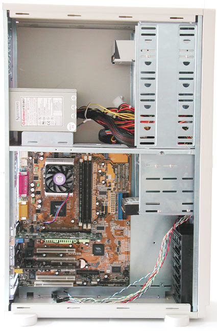
Empty case with Motherboard tray withdrawn.
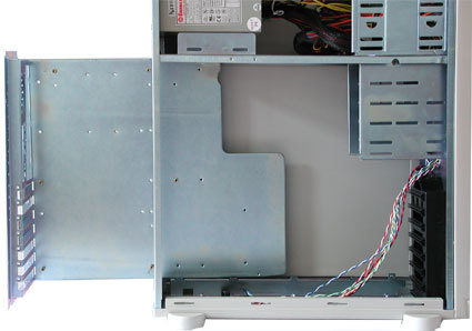
Our tower case is built to ATX specification and includes a 300-watt power supply. Two side panels can be individually removed after undoing the screws.

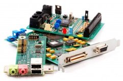
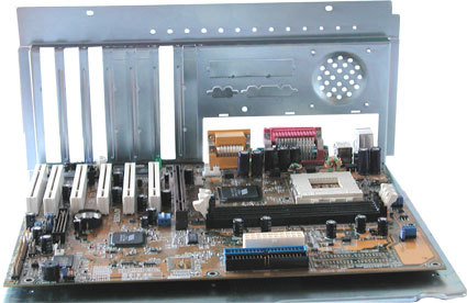
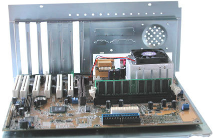
Overview of all Components (from Left to Right and Top to Bottom): Network Adapter Card, Floppy Disk Drive, CD-ROM Drive, Sound Card, Hard Disk, Ribbon Cable, Graphics Card, RAM, CPU Cooler, and Motherboard.
Empty tray with six Motherboard spacers.
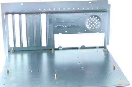
Next, screw in the spacer mounts for fixing the motherboard. The photo shows six spacers already fitted to the mounting plate. There are usually more holes drilled in the mounting plate than you actually need. There are standard locations for these holes on the mounting plate, which correspond to the holes on the motherboard. How many of these are actually used depends on the board manufacturer. Cases are normally designed to accept any motherboard. Compare the available holes with the ones on your motherboard to determine where to fit the threaded spacers.
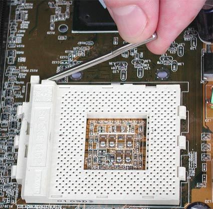
Lift the lever on the CPU socket.
when the processor is in its socket, push the lever back down.
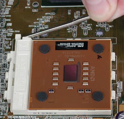
First, insert the CPU in its socket. To do this, raise the small lever at the side of the socket. If you examine the CPU from underneath, you will notice that there is a pin missing at one corner. Match this corner with the corner on the socket where there is a hole missing. The processor is keyed in this way to make sure it is inserted correctly. Please bear in mind that you should not force the CPU when inserting it! All pins should slide smoothly into the socket. If you are sure that you have positioned the CPU correctly (using the missing pin as reference), yet are unable to insert the CPU, it is likely that one of its pins is bent. If this has happened, straighten the pin using tweezers or a screwdriver. Once you have installed the processor, lock the lever back down.
Make sure that the cooler is in the correct position. Here is the cooler about to be connected with the socket.
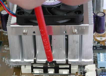
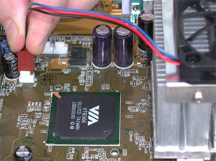
Fan Power Connection
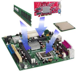
The RAM must be suitable for the motherboard. There are currently three types of RAM available: SDRAM, DDR SDRAM and RDRAM. The motherboard's chipset determines which type of RAM may be used. You will find the specification on the motherboard's box or in the motherboard manual.
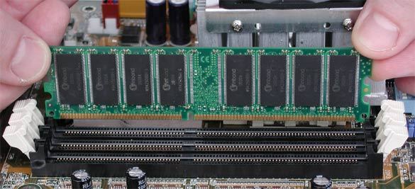
Installing RAM. A notch at the bottom of the memory module ensures that the RAM is fitted correctly. The notch is located in different places on SDRAM, DDR SDRAM and RDRAM.
DIMM memory modules have a notch underneath that lines up with a key on the memory slots. Although it is not possible to insert the modules the wrong way, you should line up the RAM with its slot before installing it. Then, carefully press the module into the slot. Caution is recommended, as too much pressure may damage certain tracks on the motherboard. It is best to push one side down first, and then the other. The notch will snap into its key as soon as one side is seated correctly. To make sure it is seated correctly, you can always take the memory module out again. Releasing the clips will pop the module out of its socket. Then, you can just lift it out.
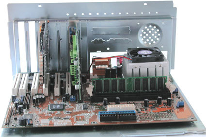
In place - Sound Card (left) and Graphics Card (center) in white PCI slots. There is room for a network card, if required.
Nowadays, Graphics cards are usually fitted in the AGP slots provided specifically for this purpose. These are brown in color, in contrast to the PCI slots, and are generally located in the center of the motherboard. PCI Graphics Cards are rarely used. Now, select a PCI slot for each of your other plug-in cards, including the Sound Card.
We assume that you have already configured your hard disk the way you want it - single, master, or slave. The photo below shows the hard disk already fitted.
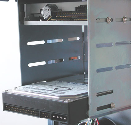
Hard Disk (bottom) and the Floppy Drive (top). You can see the screws for the drive on the side.
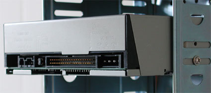
Installing a CD-ROM drive is similar to installing a Hard Disk. First, check that the jumper configuration is correct.
CD Drive In Drive Cage.
Your PC should now look similar to the one in our photograph. All key components, such as the motherboard, processor, RAM, graphics card, sound card, hard disk, CD-ROM and floppy, have been installed. Now it is time to connect the cables.
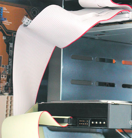
There are two main cable types: 34-pin cable for the Floppy Drive and 40-pin IDE cable (with 80 wires) for the Hard Disk and CD-ROM. Cables are always color-coded to show pin 1. Most drives also provide some kind of identification for pin 1.
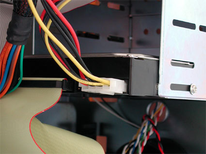
Four-pole for 5 and 12 volts. Disk drive power connector on the right next to the ribbon cable.
Power supplies are fitted with at least five plugs for delivering power to the drives.
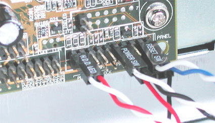
HDD LED (Hard Disk Light), Power (on/ off) Switch and RESET switch in the top row. Below: Mini Speaker.
Once you are sure that on the inside Cassing that contains the motherboard and all components were well ordered and installed correctly, then the next step we will install other components outside Cassing associated with the computer. External components such as Monitor, Mouse, Keyboard, Printer, Scanner, Modem and so forth.
After that you can proceed with installing the Operating System Windows XP, Window Vista, Window 7, LINUX or others.
Your PC is Ready....
